

As a core, easily damaged component of a reciprocating compressor, the quality of its maintenance directly determines the compressor's operational stability, efficiency, and energy-saving performance. The condition of the valves not only affects the overall air volume and discharge pressure but also leads to increased current, higher energy consumption, and a higher failure rate.
Replacing and overhauling valves is a routine part of daily equipment maintenance. Only by strictly defining maintenance standards, mastering troubleshooting methods, and following standardized assembly processes can we avoid recurring failures and abnormal shutdowns caused by inadequate maintenance or improper assembly, thus ensuring the long-term safe, stable, and economical operation of the compressor.
1. Overall Visual Inspection
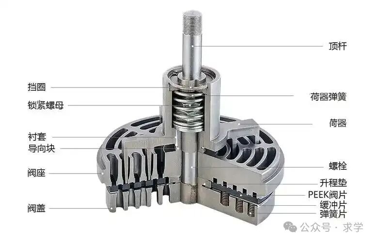
After disassembling the valve, first visually inspect the valve seat, valve plate, spring, lift limiter, and other components for cracks, deformation, rust, erosion, pitting, and obvious wear grooves. Any irreversible damage must be replaced immediately; do not attempt to repair or use it.
2. Valve Plate Inspection
Inspect the flatness and evenness of the valve plate, checking for warping, gaps, chipping, and blackening from burning. The sealing surface must be free of scratches and dents; minor burrs can be carefully repaired, but deformation, cracks, and severe wear must be discarded.
3. Spring Inspection
Check each valve spring for breakage, corrosion, fatigue, or inconsistent free height. All valve springs in the same group must be of the same specification, elasticity, and height. New and old springs must not be mixed. If the elasticity is reduced, the entire set must be replaced.
4. Sealing Surface Inspection
The sealing contact surfaces of the valve seat and valve plate should fit tightly. Minor scratches and pitting can be treated with surface grinding. After grinding, thoroughly clean to remove impurities and sand marks, ensuring a tight seal and no air leakage.
5. Channel and Carbon Deposits Cleaning
Thoroughly clean the valve flow channels and valve cavity to remove carbon deposits, oil, iron filings, and other impurities. Prevent debris from jamming the valve plate, causing poor sealing, obstructing airflow, leading to increased temperature and decreased efficiency.
6. Sealing Gaskets
The sealing gaskets for the valve seat, valve cover, and top screw cap should be replaced only after each maintenance. Reusing old gaskets is prohibited to prevent air leakage and cross-contamination.
(I) Causes of Abnormal Valve Noise
1. Fatigue, breakage, or uneven elasticity of the valve spring can cause the valve plate to not return to its original position in time, resulting in impact noise.
2. Worn, deformed, or stuck valve plates cause inflexible opening and closing during operation, producing a regular knocking sound.
3. Excessive valve lift causes frequent impacts between the valve plate and the lift limiter, generating abnormal noise.
4. Iron filings or impurities enter the valve cavity or valve interior, jamming the valve plate and causing shaking and impact sounds.
5. Improper valve assembly or loose fixing causes resonance and abnormal noise due to operational vibration.
6. Inverted intake and exhaust valves or mixed parts cause turbulent airflow, resulting in abnormal noise and backflow sounds.
(II) Causes of Valve Overheating
1. Poor valve sealing and internal air leakage cause heat accumulation during compression, leading to a rapid increase in the temperature of the valve cover and valve.
2. Stuck valve plates cause increased intake and exhaust resistance, resulting in severe throttling and heat generation.
3. Severe carbon buildup in the valve and blocked flow channels impede airflow, leading to poor heat exchange and localized overheating.
4. Spring failure leads to improper valve closure, causing continuous backflow of compressed gas and generating high temperatures.
5. Poor cylinder lubrication and carbon buildup on the valve surface result in poor heat dissipation and higher temperatures.
6. Assembly clearances not meeting standards, insufficient lift, and increased airflow cause overheating due to increased operating load.
1. Thorough Cleaning of Components
Before assembly, thoroughly clean the valve seat and valve cover sealing surfaces, removing burrs and debris to prevent leaks.
2. Use of Matching Parts
Strictly adhere to original manufacturer specifications for assembly. Parts from different manufacturers and models must not be mixed. Inlet and exhaust valve parts must not be interchanged to ensure matching accuracy.
3. Strict Control of Fitting Clearances
Control the valve lift and spring preload clearance according to equipment technical standards. Excessive lift can damage the valve plate, while insufficient lift will result in insufficient airflow and inadequate pressure.
4. Proper Installation of Sealing Components
New sealing gaskets should be placed flat, without misalignment or wrinkles. Do not arbitrarily add or remove gaskets to adjust the gap; ensure a uniform seal.
5. Diagonal and Even Tightening
After the valve is in place, some valves have locating pins; these must be aligned with the locating pins during installation. Tighten the valve cover bolts and set screws diagonally and evenly in stages, using moderate and consistent torque to prevent uneven force that could cause valve cover deformation, leaks, or cracks in the housing. Tighten the set screws and set screw caps only after tightening the valve cover.
6. Distinguishing Intake and Exhaust Valve Directions
During assembly, strictly distinguish the structure and installation position of the intake and exhaust valves; reverse installation is strictly prohibited. If a soft, cylindrical object can be pressed against the valve plate from the outside in, it is an intake valve; if it can be pressed against the valve plate from the inside out, it is an exhaust valve.
7. Assembly and Testing
After assembly, run the machine under no-load. Listen for any abnormal noises or air leaks. Gradually increase the load and observe the changes in pressure, current, and temperature. If the pressure holding is normal and there is no internal leakage, the assembly and maintenance are considered (qualified).

 EN
EN CN
CN RU
RU