


Anyone who repairs reciprocating compressors knows that the stuffing box is the core sealing component of the entire machine and a frequent source of leaks.
Many people, when disassembling the compressor, are overwhelmed by the variety of sealing rings, unable to distinguish their names or understand their uses. This leads to incorrect, incorrect, or missing installations, resulting in repeated rework.
Today, we'll disassemble each ring in the stuffing box, from the cylinder side to the crankcase side, explaining their name, structure, and function. This is all based on practical experience, so we recommend saving this for future reference during repairs.
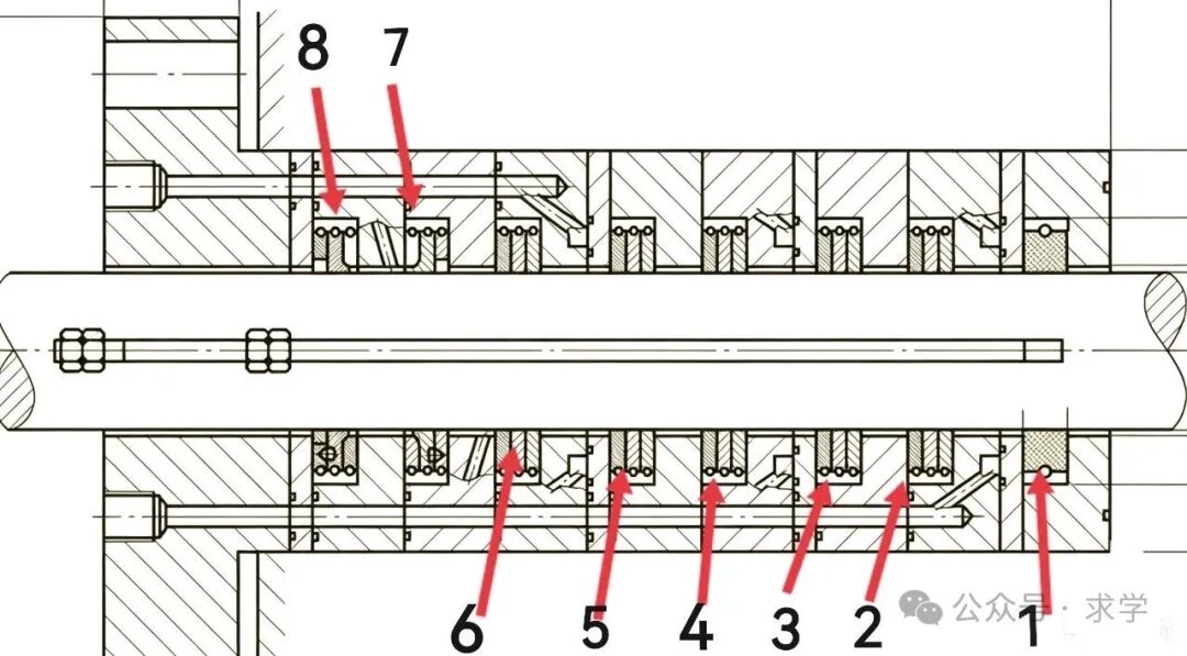
The number 1 in the diagram above represents a throttling ring. Depending on the equipment, the stuffing box may contain one or two throttling rings.
The innermost throttling ring, closest to the cylinder, is usually an integral structure and is responsible for the first stage of pressure relief and air blocking. High-pressure equipment often uses two throttling rings to reduce leakage gaps and resist the impact of high-pressure airflow.
In the diagram above, numbers 2, 3, 4, 5, and 6 show the main sealing rings of the compressor. Depending on the equipment pressure, these sealing rings are divided into several groups.
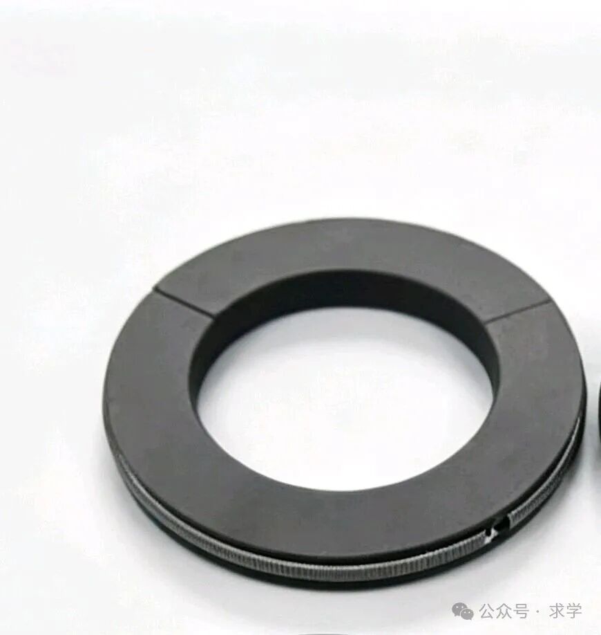
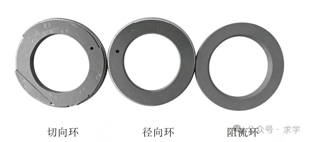
Radial Ring
Each set mainly consists of a three-lobed radial ring, a three-lobed tangential ring or a six-lobed tangential ring, and a flow-blocking ring. The cuts between the three sealing rings are staggered to ensure sealing.
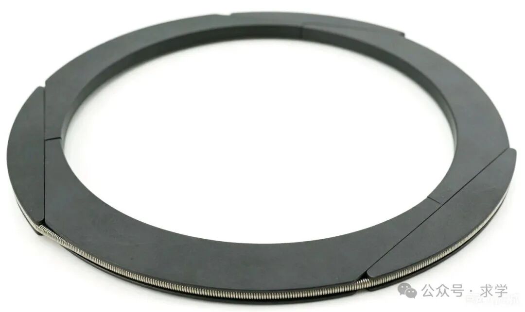
Six-lobed Tangential Ring
The sealing ring near the cylinder side is a radial ring, mainly for throttling; the middle sealing ring is a three-lobed or six-lobed tangential ring, mainly for sealing; the ring near the crankshaft side is a support and flow-blocking ring, mainly made of metal, to prevent the plastic seal from being deformed by pressure.
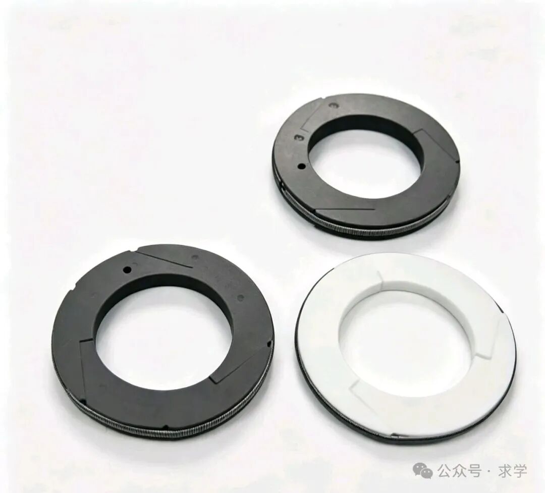
Three-lobed Tangential Ring
The flow-blocking ring inside the stuffing box has both integral and split structures. Its main function is to hold the inner sealing ring in place, preventing high pressure from damaging the PTFE ring and providing limiting and pressure-bearing protection.
Figures 7 and 8 above show leakage sealing rings, used for throttling and sealing between the isolation gas and process gas.
For compressors that compress flammable and explosive gases, leakage into the compressor body is not allowed. Nitrogen is used as an isolation gas to prevent leakage.
Nitrogen, as an isolation gas, prevents nitrogen from leaking into the compressor body and simultaneously blocks leaking process gas, collecting it in the vent pipe.
The various channels in the stuffing box are crucial for ensuring sealing safety and stable operation. Their main functions are as follows:
1. Leakage Discharge Channel: This channel directs leaked process gas from the main seal to the safety system, preventing it from etering the crankcase. It also monitors the leakage amount and assesses the seal wear condition.
2. Nitrogen Purging Protection Channel: Nitrogen gas is introduced into the isolation chamber to form a protective gas curtain, isolating process gas and lubricating oil and preventing cross-contamination, contamination, or explosion risks.
3. Oil Injection/Lubrication Channel: Lubricating oil is injected into the stuffing box to lubricate the piston rod and sealing ring, reducing wear and extending seal life.
4. Cooling Channel: Cooling medium is introduced to remove heat and prevent high temperatures from causing seal deformation and failure.

 EN
EN CN
CN RU
RU